


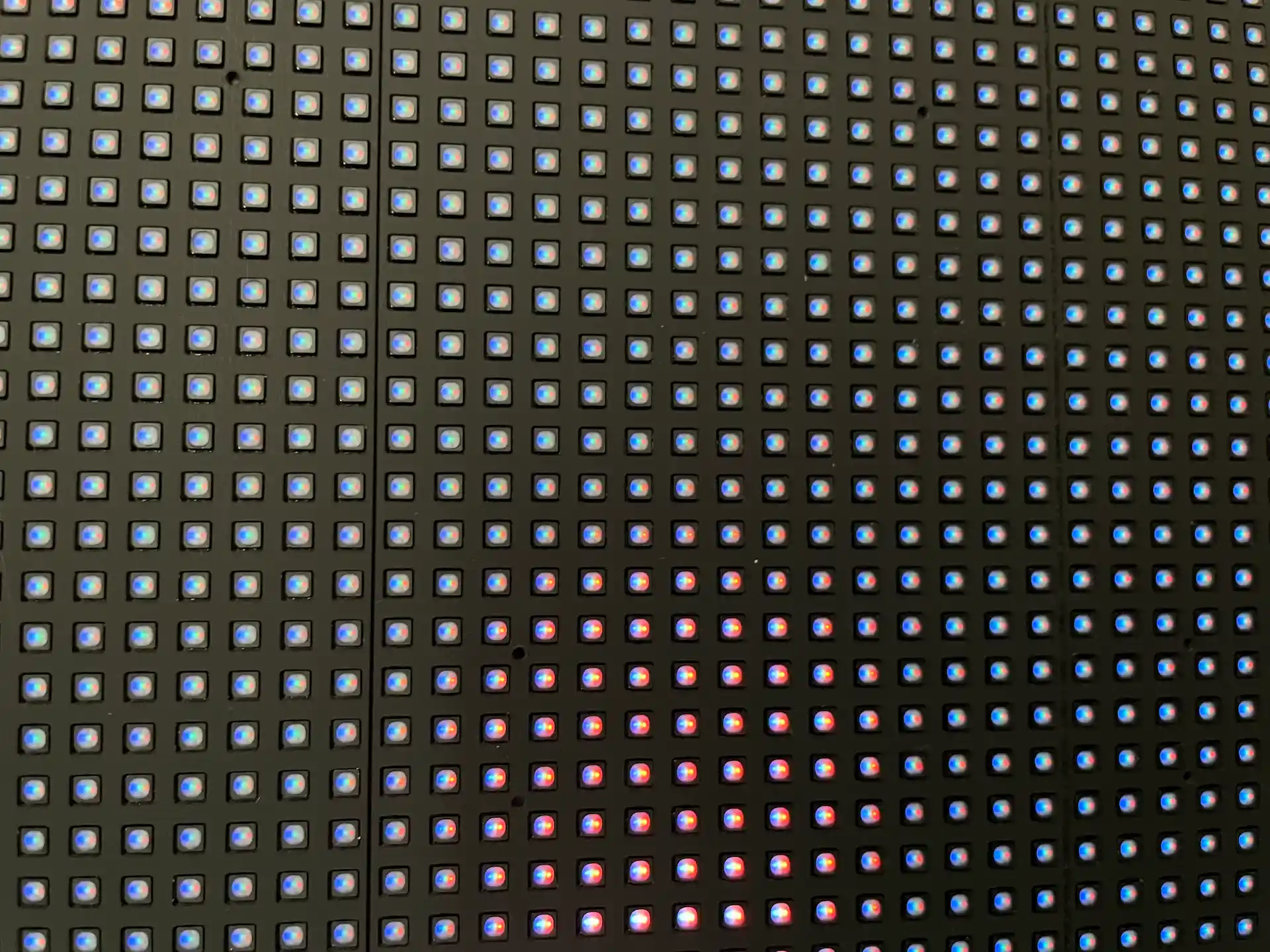
In SMD technology, light-emitting diodes of the primary colours red, blue and green are grouped and installed in a small housing. These housings are then placed on the carrier board and glued together. At the same time, the cables of the LEDs wired from above can be accommodated in the housing. As the LED packages are exposed, they can be damaged by impact, for example, but due to their design they can also be replaced individually. Due to its long availability on the market, SMD technology has become comparatively affordable and is generally found in entry-level models.
GOB LEDs are a technological advancement of the SMD design. The fully assembled circuit board is sealed with a transparent layer of epoxy resin. This layer acts as a mechanical protective shield that provides the LEDs with better protection against impact, moisture, dust and corrosion. It also converts the chips' point light sources into a homogeneous surface light, minimises the moiré effect and improves contrast values and viewing angles. However, the epoxy resin means that individual LEDs can no longer be replaced. Due to their higher resistance, the failure rate is significantly reduced compared to standard SMDs.
With COB technology, the LEDs are applied directly to a carrier board. As a relatively large amount of the black carrier board is visible between the small LEDs, COB technology is characterised by an excellent black level. In contrast to conventional wiring from above, the wiring here is from below. This process is known as a flip chip. As the LEDs are not enclosed in a housing, COB technology significantly reduces the space required by the individual pixels. This means that the pixel pitch can be reduced and the resolution increased. Especially when using micro LEDs, which are particularly small, COB LEDs enable very low pixel pitches. Finally, a thin epoxy resin coating increases the robustness of the LEDs and improves the viewing angle.
MIP technology is a hybrid packaging solution. Several MicroLED chips are first encapsulated together in one housing before they are applied to the carrier board in a similar way to classic SMD components. Just like COB, MIP uses the flip chip process, which enables optimised heat dissipation and greater reliability. A decisive advantage is that the housings can be tested before final assembly. This allows defective pixels to be removed and ensures a high level of colour homogeneity. In addition, MIP decouples the chip size from the pixel pitch, which means that one type of housing can be used flexibly for different resolutions. The individual pixel packages can be replaced during servicing. MIP thus combines the ease of maintenance of SMD technology with the high pixel density and image quality of COB technology.
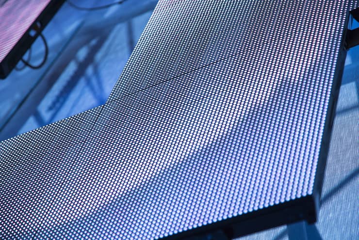

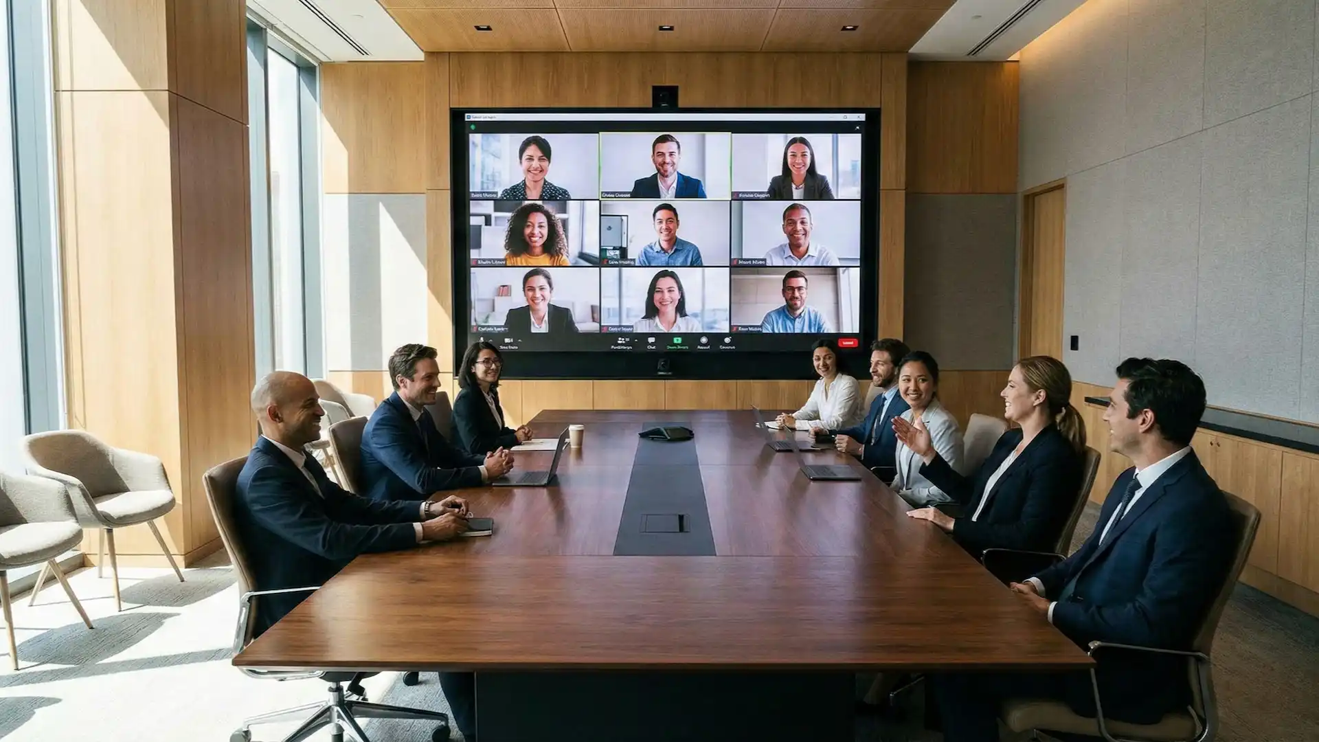


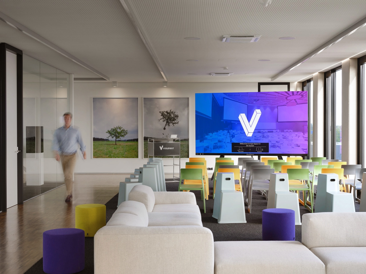
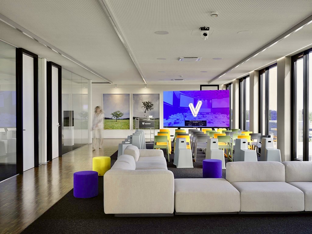
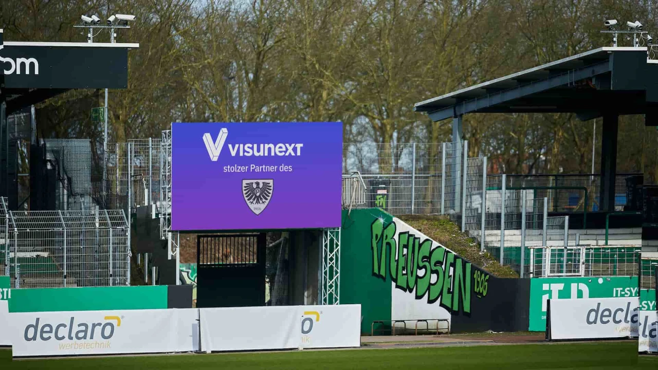
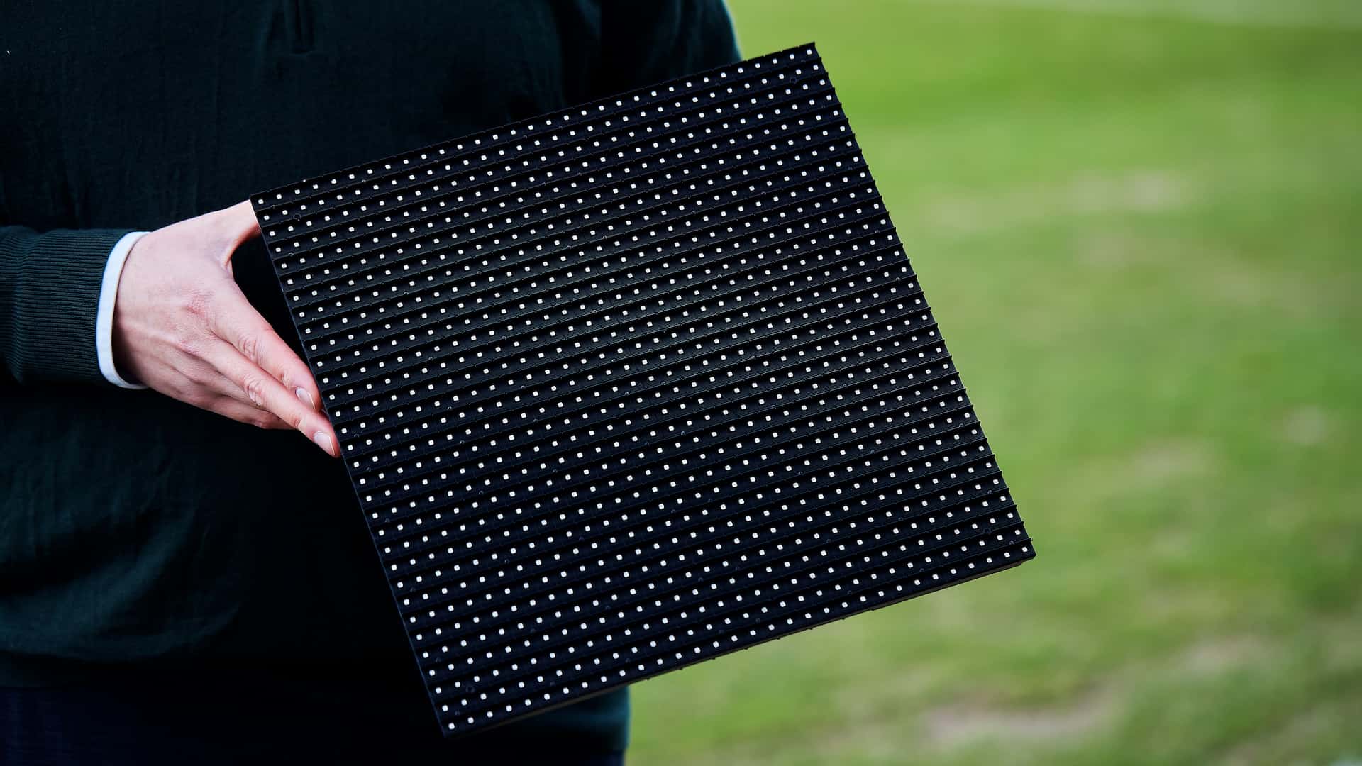
The pixelpitch or pixel pitch is the distance between the centres of two neighbouring LED pixels in millimetres. It determines the resolution and the minimum viewing distance. The rule of thumb applies to the minimum viewing distance: Pixelpitch (in mm) x 1.5 = minimum viewing distance in metres. Example: Pixel pitch 1.27 mm x 2 = 2.54 m distance. This distance ensures that the pixels can no longer be seen individually, but that the image is perceived as a homogeneous surface. In meeting rooms in particular, the image diagonal of the LED Walls should also always be taken into account to ensure that people sitting close to the wall as well as people further back in the room have an optimal view of the image.
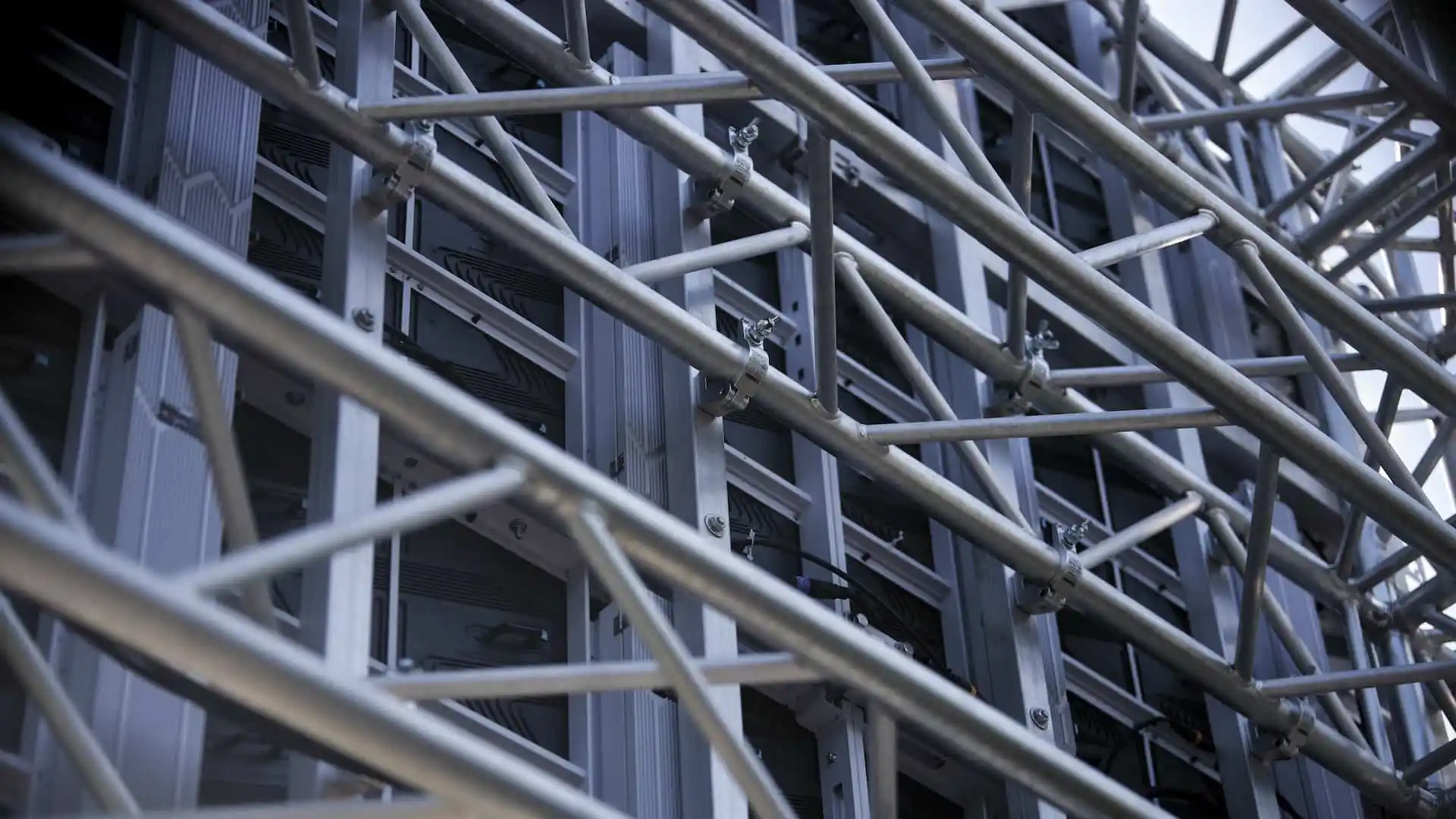
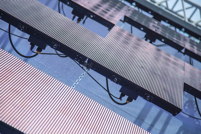
In order for an LED Wall to be installed safely, the wall or ceiling or the substructure must be able to bear the weight. Additional structural measures may be required. Despite the efficiency of the individual LEDs, LED Walls generate heat due to the many electronic components. Sufficient ventilation of the LED Wall is therefore necessary. Service and maintenance of the LED Wall must also be taken into account during installation. If maintenance from the front (front service) is not possible for the specific LED Wall model, access must be provided for maintenance from the rear (rear service).
The service life varies depending on the manufacturer and model. As a rule, an LED Wall can be used for around 60,000 to 100,000 hours until the brightness drops to 50% of the original light output. With a daily use of ten hours, this corresponds to around 16 to 27 years. However, factors such as overheating or continuous operation at full brightness can shorten the service life.
If a pixel fails, the LED Wall continues to run perfectly. However, depending on the technology (SMD, COB etc.), either a single pixel or the entire module can be replaced if necessary. In both cases, the replacement should be carried out by a specialist. Many manufacturers also supply a certain number of modules from the same batch as spare parts when purchasing an LED Wall. This ensures a homogeneous colour display even after replacement.
The price of LED Walls has fallen continuously in recent years. However, due to their significantly longer service life and lower maintenance and replacement costs compared to other technologies, LED Walls are often the more economical alternative over a period of several years. The exact costs of purchase and operation depend largely on the size and technology of the LED Wall and its power consumption.
The LED controller (also known as the video processor or sending card) acts as the central control element of the LED Wall. As the crucial link between the image source and the display, the controller processes the input signal (e.g. via HDMI) so that it is distributed exactly to the millions of pixels of the modules. The controller handles the scaling to individual wall formats, synchronises the modules for a smooth display and calibrates colours and brightness for a homogeneous image. While classic LED Walls often require external hardware in the server cabinet, the controller is already integrated in All-in-One LED Walls.